 ADC"/>
CCS5.4+Proteus8的F28027实践课七、ADC
吃完饭回来了,现在开始我们的ADC实践操作。
直奔主题我们,那就是ADC编程操作流程是怎么样的。
其实通过上节理论课的学习,大家心里都应该有了模糊的感觉,一般的步骤如下:
1、使能ADC模块时钟( PCLKCR0.ADCENCLK =1)
2、启动模拟电路、带隙和参考源,ADCCTL1寄存器(ADCPWDN, ADCBGPWD, ADCREFPWD位=1)
3、使能ADC模块(ADCCTL1.ADCENABLE=1)
4、ADC中断相关设置(参考PIE)
5、模拟IO引脚复用设置(AIOMUX1)
6、SOC配置(触发、通道、采样窗口)
7、编写中断ISR(读取ADC结果)
了解了操作步骤,那我们就要了解相关的寄存器,由于寄存器又比较多,我这里就不一一讲述,大家直接去看手册就行了
了解了寄存器,下面就要看下具体的操作时序图了:
顺序采样的迟中断
顺序采样的早中断
同步采样的迟中断
同步采样的早中断
好了,时序图也看完了,我们现在来参考时序图写程序了。
我们先来个简单的,顺序采样的迟中断。
既然是ADC,那我们这节课肯定用到了TI提供的F2802x_Adc.c文件,另外,还要显示,也需要把我们上节课整理的F2802x_LCD12864.c文件。
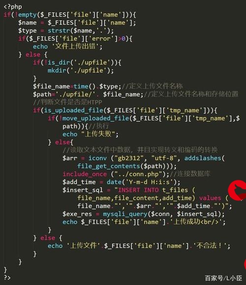
首先我们一起来看下ADC初始化函数InitAdc()
void InitAdc(void)
{extern void DSP28x_usDelay(Uint32 Count);// *IMPORTANT*// The Device_cal function, which copies the ADC calibration values from TI reserved// OTP into the ADCREFSEL and ADCOFFTRIM registers, occurs automatically in the// Boot ROM. If the boot ROM code is bypassed during the debug process, the// following function MUST be called for the ADC to function according// to specification. The clocks to the ADC MUST be enabled before calling this// function.// See the device data manual and/or the ADC Reference// Manual for more information.EALLOW;SysCtrlRegs.PCLKCR0.bit.ADCENCLK = 1;(*Device_cal)();EDIS;// To powerup the ADC the ADCENCLK bit should be set first to enable// clocks, followed by powering up the bandgap, reference circuitry, and ADC core.// Before the first conversion is performed a 5ms delay must be observed// after power up to give all analog circuits time to power up and settle// Please note that for the d
更多推荐
CCS5.4+Proteus8的F28027实践课七、ADC


发布评论